T: +86-18156545248
E: info@wnksensor.com
E: info@wnksensor.com
5F, Bldg. 2A, Mingzhu Industrial Park Hefei 230000, China
Views: 0 Author: Site Editor Publish Time: 2026-05-27 Origin: Site
Critical environment control involves extremely high stakes where everyday precision remains absolute. Improper pressurization quickly leads to dangerous cross-contamination, failed GMP audits, and severely compromised product yields. Framing this underlying technical challenge reveals a highly complex reality. Specifying a measurement device is never just about grabbing a standard catalog number off a shelf. You must closely align sensitive sensor capabilities to specific Building Management System (BMS) architectures. Facility teams must also constantly navigate strict industry compliance standards expected by organizations like ISPE and the FDA. This comprehensive article provides facility engineers and managers an evidence-based evaluation framework. We will thoroughly explore how you should evaluate pressure range, signal output types, and physical display options. You will learn actionable steps to ensure daily system stability, absolute measurement accuracy, and constant audit readiness.
Range vs. Accuracy: Selecting an excessively wide measurement range degrades low-end accuracy; specify ranges as close to normal operating conditions as possible.
Output Protocols: Analog (4-20mA/0-10V) remains standard for legacy systems, while RS485/Modbus is increasingly necessary for data-heavy, scalable cleanroom architectures.
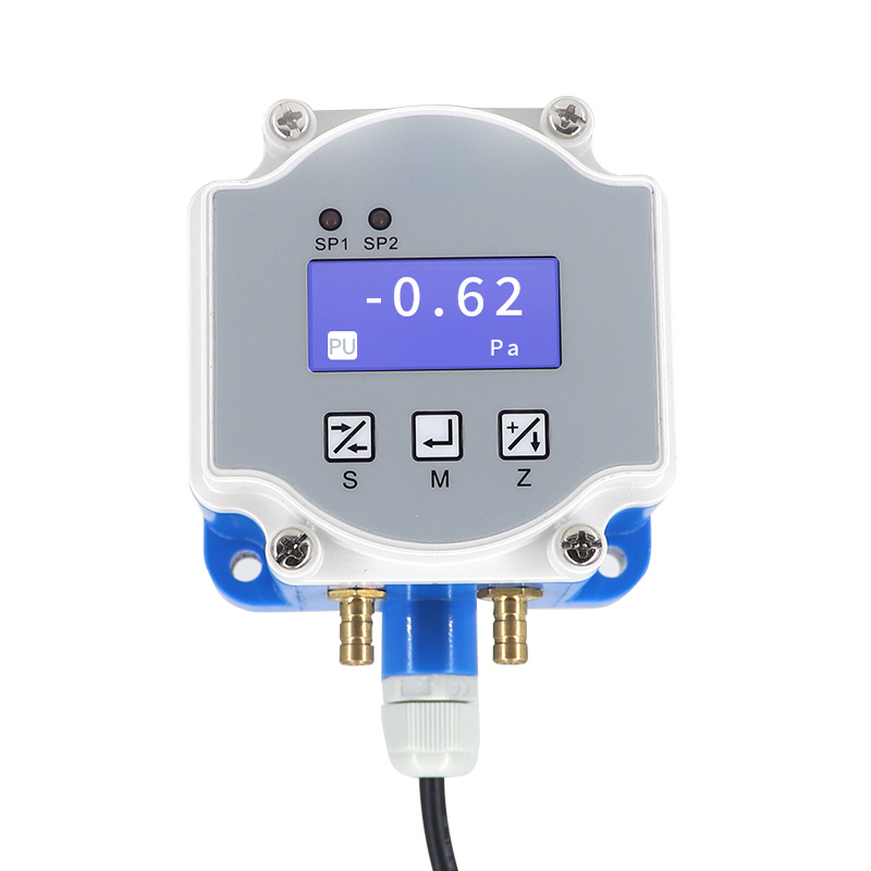
Display Utility: Local displays are critical for daily cleanroom operator checks and audit compliance, whereas blind transmitters reduce costs in hidden HVAC duct applications.
Modern cleanrooms rely heavily on a concept known as cascade pressurization. This strategy maintains specific positive or negative pressure gradients between adjacent architectural zones. Maintaining these gradients forms an invisible barrier against microscopic airborne particles. Positive pressure actively pushes dirty air away from highly sterile spaces. Conversely, negative pressure safely contains hazardous biological agents inside dedicated isolation rooms. You need exact measurements to sustain these critical invisible boundaries.
Industrial Air Handling Units (AHUs) also demand strict oversight. Filter monitoring prevents unexpected mechanical system failures. As HEPA filters naturally clog over time, differential pressure across the filter bank predictably increases. You need continuous, reliable sensors to track this degradation closely. Waiting for a manual pressure check often results in restricted airflow and compromised room cleanliness.
Sensor drift represents a massive operational liability across these environments. Drift forces maintenance teams into frequent, unplanned recalibrations. It rapidly increases overall system downtime and consumes valuable labor hours. More importantly, baseline drift triggers frustrating false alarms across your central BMS network. Operators eventually begin ignoring recurring alarms, which creates severe safety risks.
Regulatory compliance introduces incredibly strict data expectations. Agencies like the FDA expect continuous, verifiable, and secure data logging. Auditors aggressively scrutinize your historical environmental records during facility inspections. A reliable measurement device acts as a core compliance asset. It defends your operation during surprise audits. Reliable baseline data physically proves your critical environments remain continuously stable and perfectly safe.
Over-specifying a measurement range creates severe systemic accuracy issues. Engineers often choose standard wide ranges simply out of habit. This careless practice destroys critical low-end precision. Matching the precise measurement range to your specific application limits is absolutely crucial. You must select hardware limits tightly surrounding your normal operating conditions.
Common application measurement ranges typically include:
Cleanroom Room-to-Room Pressurization: Demands ultra-low measurement scales. Common engineering selections span ±25 Pa, ±50 Pa, or ±0.1 to 0.25 inW.C.
HVAC Filter Monitoring: Expects slightly higher pressure changes due to heavy airflow. Standard selections run from 0-500 Pa up to 0-1000 Pa. Filter load expectations dictate the exact upper limit.
Isolation Enclosures: Usually require tight negative bands, often sitting safely between -15 Pa and -30 Pa.
The dreaded accuracy penalty happens because sensor error margins scale proportionally. Internal sensor accuracy usually reflects a fixed percentage of Full Scale (FS). Imagine specifying a 0-1000 Pa range for a delicate 15 Pa room differential. A standard 1% FS error equals ±10 Pa of uncertainty. This massive error margin makes monitoring a 15 Pa target virtually impossible. Your BMS will record wild, inaccurate swings simply due to poor hardware scaling.
Complex operations sometimes require asymmetric or bi-directional measurement capabilities. Facility pressure flows might completely reverse during specific chemical cleaning phases. You should specify a bi-directional Low Differential Pressure Transmitter to confidently handle these sudden shifts. A ±50 Pa unit captures dynamic environmental changes without losing baseline accuracy. It provides essential flexibility during complex vaporized hydrogen peroxide (VHP) decontamination cycles.
Selecting the right output protocol directly impacts your entire network architecture. You must align the signal type securely to your existing controller infrastructure. Making the wrong choice requires expensive signal converters or complete rewiring projects.
The 4-20mA current loop protocol historically dominates heavy industrial environments. It delivers incredibly high immunity to ambient electrical noise (EMI/RFI). Current loops easily push reliable signals across massive facility footprints without degrading. However, current loops remain strictly limited to transmitting one process variable per wire pair. They also require slightly more complex wiring loop diagrams.
Voltage outputs like 0-10V or 0-5V offer straightforward integration. Legacy building controllers accept these simple voltage signals natively. Unfortunately, raw voltage drops severely over long cable distances. You should restrict voltage signals strictly to local, short-run installations. Never run a 0-10V line across a sprawling pharmaceutical campus.
Digital protocols like RS485 or Modbus RTU actively support scalable modern facilities. They allow you to daisy-chain multiple network devices along a single communication trunk. This modern approach drastically reduces physical cabling expenses. Digital networks also transmit rich diagnostic data alongside standard pressure readings. Implementing them requires strict network compatibility and baseline digital configuration skills.
Output Signal | Primary Advantage | Notable Limitation | Best Application Use Case |
|---|---|---|---|
4-20mA (Current) | High noise immunity (EMI/RFI) | Transmits only a single process variable | Long cable runs in heavy industrial spaces |
0-10V (Voltage) | Simple legacy controller integration | Highly susceptible to cable voltage drop | Short-run, highly localized HVAC panels |
RS485 / Modbus | Daisy-chaining and deep diagnostic data | Requires dedicated network configuration skills | Data-heavy, scalable modern cleanrooms |
Physical measurement displays serve a highly specific operational purpose. Choosing between integrated screens and blind units heavily dictates your daily facility workflows. You must evaluate human interaction requirements before finalizing hardware purchases.
Integrated LCD or LED displays greatly benefit high-traffic critical zones. You should install them directly outside cleanroom corridors, biosafety cabinets, and isolation rooms. These bright displays allow operators to visually verify pressure states before opening secure doors. This simple visual check prevents accidental cross-contamination events. Local screens also provide immediate diagnostic feedback during formal compliance audits. Visiting auditors expect rapid visual confirmation of stated environmental limits.
Blind transmitters intentionally lack physical screens entirely. They belong hidden inside drop ceilings, AHU enclosures, and inaccessible mechanical rooms. Removing the complex display naturally lowers the initial hardware unit cost. Furthermore, blind units actively prevent unauthorized staff from physically tampering with local settings. When you deploy a blind Micro Differential Pressure Transmitter, you forcefully centralize operational control. It strictly forces your facility team to rely on the central BMS for definitive data truth. This strict centralization ensures highly consistent historical record-keeping.
Initial hardware specification represents only half the engineering challenge. Harsh physical installation realities quickly expose underlying sensor weaknesses. You must anticipate field conditions to guarantee long-term stability.
Zero-drift remains the most common field failure point worldwide. High-end units feature internal auto-zero solenoids to correct minor baseline deviations automatically. Manual zero-push buttons work perfectly fine for easily accessible wall locations. However, auto-zero capabilities prove absolutely critical for sensitive sensors hidden inside deep ceiling ductwork.
Mounting orientation aggressively impacts micro-differential sensor performance. These highly sensitive internal diaphragms respond strongly to physical gravity. Mounting a delicate unit sideways artificially alters its baseline resting state. You must always mathematically zero the unit directly after final physical installation. Zeroing it on a workshop bench guarantees wildly inaccurate field readings once mounted.
Pneumatic tubing introduces significant physical vulnerabilities. Hidden condensation frequently builds up inside cold impulse lines. Soft pneumatic tubes frequently kink during routine ceiling maintenance. Extreme temperature fluctuations expand trapped air inside blocked lines. These physical tubing issues perfectly mimic internal electronic sensor failures. If your HVAC Differential Pressure Transmitter suddenly fluctuates wildly, always check the physical tubing first.
Scheduled calibration cycles permanently dictate your long-term maintenance burden. Standard industrial sensors demand strict annual factory calibrations to ensure compliance. High-stability digital sensors increasingly offer extended two-to-three-year compliance cycles. Adopting extended cycles drastically reduces expensive specialized labor costs and overall facility downtime.
Purchasing the right Pressure Transmitter requires a highly systematic approach. Avoid selecting hardware based solely on brand familiarity. Follow this structured framework to ensure successful, seamless facility integration.
Step 1: Audit the Environment: Carefully determine the precise required pressure delta. Note extreme ambient operating temperatures. Check for corrosive ambient gases or excessive moisture near the final installation zone.
Step 2: Align with Architecture: Match the internal output signal directly to your existing PLC or BMS infrastructure. Decide firmly between analog current loops and digital network protocols early in the design phase.
Step 3: Evaluate Long-Term Reliability: Thoroughly review calibration difficulty, physical ruggedness, and specific warranty terms. High-quality field instruments drastically reduce unexpected maintenance interventions. Focus strongly on Mean Time Between Failures (MTBF) ratings.
Step 4: Proof of Concept (PoC): Test a small initial batch of three to five identical units. Deploy them in a single localized engineering zone. Verify complete BMS integration and test field zero stability before committing to a massive facility-wide rollout.
Specifying a precision measurement device carefully balances absolute accuracy against strict network compatibility. You must also weigh everyday physical maintenance realities carefully before finalizing designs. A poorly chosen device generates endless false alarms and compromises overall facility safety.
Choosing the correctly scaled pressure range aggressively prevents false data generation at the foundational level. Selecting the optimal signal output and physical display format ensures seamless daily operations for your staff. Every specification detail matters when designing critical environments.
Do not guess when controlling sensitive critical environments. Consult a qualified application engineer to review your specific facility blueprint closely. Request a detailed technical datasheet to verify standard compliance before issuing final purchase orders.
A: Standard units measure high pressures (bar/PSI) against standard atmospheric pressure. Micro differential units measure minute differences (Pa/inW.C.) between two distinct internal building zones. They require highly sensitive capacitive or piezoresistive diaphragms to detect these tiny shifts accurately. This extreme engineering sensitivity makes them essential for reliable cleanroom cascade control.
A: Rapid fluctuations usually result from highly turbulent airflow directly near the sensing probe. Loose tubing connections or un-damped sensor software settings also cause heavy signal noise. You can usually resolve this field instability by properly adjusting the transmitter's internal response time. This simple tuning process is commonly known as signal damping.
A: Strict GMP guidelines dictate the ultimate schedule based on formal operational risk assessments. However, most pharmaceutical and semiconductor applications explicitly require strict annual calibration. This yearly check visually verifies baseline zero stability and ensures full-scale accuracy remains well within acceptable regulatory compliance limits.
A: We strongly advise against it. Voltage signals suffer severe electronic degradation over long physical distances. They are also highly susceptible to surrounding electromagnetic interference from heavy motors. For distances exceeding 50 feet, you should rely strictly on 4-20mA current loops or RS485 digital outputs. These remain the proven, robust industry standard.