


T: +86-18156545248
E: info@wnksensor.com
E: info@wnksensor.com
5F, Bldg. 2A, Mingzhu Industrial Park Hefei 230000, China
Views: 0 Author: Site Editor Publish Time: 2026-07-08 Origin: Site


Selecting the wrong pressure transmitter output signal leads to severe consequences in automated systems. It causes sudden data loss, erratic PLC readings, and unnecessary plant downtime. In heavy industrial environments, electromagnetic interference (EMI) actively works against signal integrity. Extremely long cable runs degrade poorly chosen signals. You cannot afford blind spots in critical process control loops. A reliable output signal must match your facility's existing control architecture perfectly. It must survive the local EMI environment without data corruption. It must also support the necessary diagnostic capabilities for modern maintenance routines. This comprehensive guide breaks down the harsh engineering realities of sensor signals. We explore distance limitations and deployment risks of 4-20mA, 0-10V, HART, and RS485 protocols. You will learn how to specify the exact right sensor for your application. We will help you avoid common wiring traps and secure flawless data transmission across your entire plant.
0-10V is cost-effective for short-distance (<50m), low-noise environments like HVAC panels.
4-20mA remains the industrial standard due to its high EMI immunity, long-distance viability (up to 1000m), and "live zero" fault detection.
HART overlays digital multi-variable data onto standard 4-20mA wiring, ideal for retrofitting legacy systems with smart diagnostics.
RS485 (Modbus) excels in multi-device daisy-chain networks requiring extensive data transmission, supporting distances up to 1200m.
We classify these two options as pure analog signals for primary control. Voltage signals like 0-10V carry significant structural flaws in heavy industry. Long cable runs create natural wire resistance. This resistance causes severe voltage drops across the circuit. If a sensor outputs 10V, the PLC might only receive 9V. You lose immense accuracy immediately. They remain highly vulnerable to electromagnetic interference. Nearby motors, contactors, or variable frequency drives easily distort voltage readings. You should strictly limit 0-10V outputs to distances under 50 meters. They belong in highly controlled, clean environments. Building Automation Systems (BAS) and simple HVAC panels use them successfully.
In contrast, industry standardized on current loops for very practical reasons. Current remains constant throughout an entire closed loop. It ignores line resistance completely. This makes it highly immune to voltage drops over long runs. You can push these analog signals up to 1000 meters without signal degradation.
When you install a 4-20mA Pressure Transmitter, you benefit from the "live zero" concept. Current loops never start at 0mA. The baseline 4mA provides continuous parasitic power. This drives the internal circuitry of a 2-wire transmitter. More importantly, it gives you instant, built-in diagnostics. A 0mA reading instantly indicates a broken wire. It flags a power failure immediately. It never means zero pressure.
Understanding loop load resistance remains critical for 4-20mA networks. Every device in the loop adds electrical resistance. The wire itself adds resistance. The PLC input card adds resistance. Your power supply must push current through all this combined load. If the total resistance exceeds the power supply capacity, the signal clips. It might reach 18mA and suddenly stop rising. You must calculate your maximum allowable loop load before installation. Standard 24VDC supplies typically handle 600 ohms easily. Always verify this math during the design phase.
Finally, current loops support intrinsic safety protocols seamlessly. You can easily pair them with Zener barriers. This protects electrical circuits in explosive and highly hazardous environments.
Running 0-10V signals across factory floors alongside AC power lines.
Failing to account for loop load limits on long 4-20mA runs.
Using unshielded cables for sensitive analog voltage measurements.
Assuming a 0mA reading simply means zero pressure inside a tank.
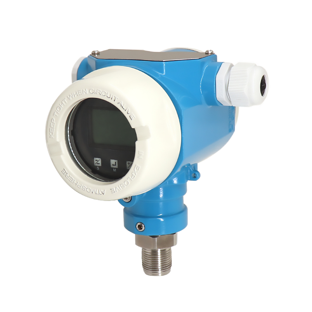
HART falls into the hybrid analog-digital communication category. It bridges the gap between old wiring and new data systems. How it works requires some technical expertise. HART uses Frequency Shift Keying (FSK). This standard relies on the Bell 202 telecommunications protocol. It superimposes a low-level digital signal over standard 4-20mA wiring. It uses 1200Hz to represent a binary "1". It uses 2200Hz to represent a binary "0". This happens continuously without disrupting your primary analog control signal. Low-pass filters block the high-frequency digital noise from the PLC analog input.
Decision makers love the features-to-outcomes translation. You need no scaling logic inside the PLC. You can read exact pressure, temperature, and sensor health directly. The digital protocol delivers primary, secondary, and tertiary variables (PV, SV, TV). You skip calculating PLC scaling blocks entirely.
Remote configuration saves enormous maintenance time. Engineers can calibrate devices from the central control room. You can adjust zero and span settings remotely. You simply use a handheld HART communicator or software like Pactware. This eliminates hazardous field trips to dangerous plant areas.
However, you must manage specific implementation risks. The "noise trap" catches many inexperienced installers. Running unshielded 4-20mA cables near 120VAC power lines induces electrical noise. This noise often falls into the exact 1200Hz to 2200Hz HART frequency band. It tricks a HART Pressure Transmitter into a communication freeze. The device stops sending its digital data. You must always specify shielded twisted-pair cables. Ground the shield at one end only to prevent ground loops.
This represents pure digital, bi-directional communication. RS485 Modbus fits modern data-heavy applications perfectly. You should evaluate it on a few key dimensions. Scalability is its strongest architectural asset. You can daisy-chain up to 32 devices on a single two-wire bus. Some repeaters allow even more nodes. This drastically reduces massive cabling costs. You avoid running individual point-to-point wires for every single sensor in the plant.
Distance and transmission speed also stand out. Reliable data transmission extends up to 1200 meters. This makes it ideal for sprawling industrial facilities. Large tank farms and extended pipeline monitoring systems rely heavily on it.
Implementation realities require strict attention to electrical detail. You must design a proper network architecture. Each device requires a specific address allocation. Duplicate addresses will crash the entire communication bus immediately.
Crucial engineering details matter greatly here. You must include 120-ohm terminating resistors at both ends of the bus. They absorb electrical energy at the wire ends. This prevents signal reflection and sudden data corruption. Skipping this step guarantees intermittent communication failures.
Troubleshooting RS485 networks requires specialized tools. A standard multimeter cannot read high-speed digital packets. You need a protocol analyzer or an oscilloscope. When data drops, engineers usually look at the baud rate first. Every device on the daisy chain must share the exact same baud rate. Common speeds include 9600 or 19200 bps. A single mismatched device brings down the entire network segment. Additionally, watch out for reversed polarity on the data lines. A swapped A and B wire creates immediate communication loss.
Another common mistake involves network topology. RS485 demands a strict daisy-chain layout. Star topologies or long "stub" drops cause massive signal degradation. You must route the bus directly from one sensor to the next.
Selecting an Industrial Pressure Transmitter requires a systematic approach. The right choice depends on distance, noise, and data requirements. Every facility possesses a unique electrical footprint. You must match the transmitter output to your specific constraints.
We built an evaluation matrix to simplify your shortlisting logic. Review the chart below to match outputs to your scenarios.
Application Requirement |
Recommended Output Signal |
Primary Technical Benefit |
|---|---|---|
Cable Distance > 100m or High EMI Environment |
4-20mA Current Loop |
Unbeatable analog stability and high noise immunity over long runs. |
Multiple Variables (Pressure + Temp) on Legacy Wiring |
HART Protocol |
Delivers smart digital diagnostics without replacing existing plant cabling. |
Connecting 10+ Sensors on One Run to SCADA |
RS485 / Modbus RTU |
Massive cabling cost reduction via multi-node daisy-chain networking. |
Confined Panel, Clean Environment, Strict Budget |
0-10V Voltage Signal |
Highly cost-effective for very short distances under 50 meters. |
Forward-thinking facilities are adopting modern hybrid architectures. They refuse to rely on just one method. They use 4-20mA for instantaneous, fail-safe primary loop control. It guarantees the valve closes when pressure spikes. Simultaneously, they tap the HART or RS485 output for cloud-based predictive maintenance. They route this digital data to secondary asset management systems. This future-proofs the installation completely. You get analog reliability combined with digital intelligence.
Demonstrating field expertise means understanding the underlying math. You must translate a raw current reading back to physical pressure. The PLC relies on this mathematical scaling.
Use this standard industry formula:
P = (I - 4) * (P_max - P_min) / 16 + P_min
Where:
P equals the calculated physical pressure.
I equals the measured current in milliamps.
P_max equals the maximum range of the sensor.
P_min equals the minimum range of the sensor.
Consider a real-world example. You install a 0 to 1000 kPa transmitter. Your PLC reads a 12mA signal. Apply the formula. The calculation looks like this: (12 - 4) * (1000 - 0) / 16 + 0. The result equals exactly 500 kPa. This perfectly linear relationship makes PLC programming highly predictable.
Routine calibration maintains signal integrity over time. Sensors experience natural mechanical fatigue. Their electronic components drift slightly as they age. You should verify the output signal against a known pressure standard annually. Document the "as found" and "as left" mA values. This historical data reveals long-term drift trends. It helps you schedule proactive replacements before sudden failures occur.
Troubleshooting signal fluctuations requires a highly disciplined approach. If your Pressure Transmitter shows erratic readings, do not guess. Apply a rigid 4-step exclusion method:
Verify power supply stability under full load. A sagging 24VDC supply causes current loops to drop out randomly.
Check for hidden ground loops. Ensure you practice single-point grounding on all cable shields.
Inspect all cable shielding for physical damage. Look for broken drain wires inside junction boxes.
Swap the unit with a known calibrated spare. This isolates actual sensor drift from deeper DCS input card issues.
Following these steps prevents unnecessary sensor replacements. It targets the root cause of electrical noise quickly.
Signal selection remains as critical as the physical sensor diaphragm. You cannot ignore the electrical realities of your plant. The 4-20mA signal remains the unbreakable industrial workhorse. It handles long distances and heavy noise effortlessly. Meanwhile, HART and RS485 protocols unlock vital diagnostic data. They provide the multi-variable insights required for modern Industry 4.0 operations.
Evaluate your facility's wire routing carefully. Assess your specific EMI risks and DCS compatibility before purchasing. Consult with an instrumentation specialist to review your electrical specifications. Taking these proactive steps ensures proper selection. It guarantees long-term accuracy and prevents costly communication failures across your facility.
A: Some advanced models support simultaneous output, but utilizing both can occasionally introduce noise, slightly degrading the 4-20mA analog precision. It is generally recommended to rely on one primary communication method per unit.
A: RS485 reaches up to 1200m; 4-20mA supports up to 1000m (depending on loop load resistance); 0-10V is strictly limited to 50m to avoid voltage drops.
A: Because the sensor operates on a "live zero" (4mA represents the lowest pressure), a reading of 0mA at the PLC instantly flags a broken wire or power failure, allowing for rapid diagnostics.


