T: +86-18156545248
E: info@wnksensor.com
E: info@wnksensor.com
5F, Bldg. 2A, Mingzhu Industrial Park Hefei 230000, China
Views: 0 Author: Site Editor Publish Time: 2026-07-01 Origin: Site
Pump failures are rarely unavoidable wear-and-tear. You can usually trace them back to an expensive, preventable event caused by a lack of real-time fluid and pressure monitoring. Modern industrial and municipal water management is rapidly shifting toward intelligent monitoring. By leveraging Variable Frequency Drives (VFDs) and precision instruments, facilities actively reduce energy waste while extending asset lifecycles. Unfortunately, many operators still rely on outdated visual gauges or blind mechanical relays, leaving high-value infrastructure exposed to sudden hydraulic changes.
We wrote this article to provide a clear path forward. You will discover a realistic, engineering-focused framework for selecting and implementing the exact monitoring equipment your facility needs. We will break down how to effectively defend against hydraulic shock, dry running, and cavitation to protect your critical infrastructure from catastrophic damage.
Catastrophic Prevention: A correctly integrated water pressure sensor can detect dry running conditions before critical components (like magnetic drive couplings) destroy themselves in under 15 seconds.
Hydraulic Shock Mitigation: Utilizing sensors with ceramic layered cores and water hammer dampeners prevents pressure spikes (often 10x normal operating pressure) from destroying the monitoring equipment itself.
Holistic Evaluation: True pump protection requires choosing between (or combining) mechanical low-pressure cutoffs, flow switches, and continuous monitoring via a water pressure transmitter based on the pump’s control mode (VFD vs. fixed speed).
Environmental Resilience: Commercial-grade, hermetically sealed pressure sensors outlast low-cost alternatives by decades, especially in highly corrosive outdoor or wastewater environments.
Running unprotected pumps creates massive hidden financial liabilities. When facilities fail to implement continuous monitoring, they invite disastrous operational consequences. You might experience catastrophic seal failures, flooded pump rooms, and excessive production downtime. Repairing a destroyed municipal pump often costs tens of thousands of dollars. These repairs eclipse the initial cost of installing proper protection devices. Passive monitoring no longer suffices for modern utility demands.
Industry data clearly demonstrates the value of intelligent pressure management. When operators apply precise control over water distribution, they dramatically improve asset efficiency. Optimal regulation can reduce new pipeline bursts by over 50 percent. Furthermore, matching pump speed to exact demand lowers overall energy consumption by 20 to 40 percent. These metrics prove we must treat sensors as proactive energy-saving tools, rather than mere diagnostic accessories.
Conducting a proper risk assessment ensures you deploy the right technology for the right application. You must establish distinct criteria to justify hardware upgrades. For example, a high-value VFD pump requires an advanced Water Pressure Sensor to enable continuous feedback loops. Conversely, a low-budget agricultural irrigation system might only require a basic mechanical low-pressure cutoff. Balancing asset value against sensor cost dictates your best protective strategy.
Dry running occurs when a pump operates without sufficient fluid. This fluid normally provides essential cooling and lubrication for the internal mechanical seals and bearings. Without it, friction generates intense heat almost immediately. The internal components expand, warp, and eventually seize. You cannot depend on human intervention to stop this process fast enough.
The timeline of destruction moves incredibly fast. Sensitive equipment suffers catastrophic damage rapidly. Magnetic drive pumps, heavily utilized in chemical processing, can suffer complete magnetic coupling failure in just 10 to 15 seconds of dry running. Implementing high-speed automatic shutdown logic remains your only viable defense against fluid starvation.
Cavitation destroys impellers through repeated, microscopic explosions. It happens when localized pressure drops below the fluid's vapor pressure, causing the water to boil at ambient temperatures. These gas bubbles flow into higher-pressure zones within the volute and collapse violently. The resulting shockwaves pit the metal surfaces, eventually chewing through thick steel casings.
Predicting this phenomenon requires accurate suction-side data. A precision Water Pressure Transducer feeds continuous data into the controller. The PLC uses this data for Net Positive Suction Head (NPSH) calculations. By monitoring the NPSH margin, the system can predict cavitation conditions and automatically reduce motor speed before impeller pitting occurs.
Water hammer represents the most violently destructive force in fluid transport. It triggers when flowing water hits a sudden obstruction. Common triggers include rapid valve closures, sudden pump starts or stops, and high-elevation discharges dropping more than 20 meters. The fluid's kinetic energy converts instantly into static pressure, generating a shockwave that travels backward through the pipe.
This threat severely compromises system integrity. The sudden energy conversion forces pressure spikes up to tens of times the normal operating load. A 100-PSI system might suddenly experience a 1,000-PSI shockwave. These spikes destroy valves, blow out pipe joints, and rupture unprotected sensor diaphragms instantly. You must engineer specific physical safeguards to mitigate hydraulic shock.
Protecting a complex fluid system demands a layered approach. By integrating VFD power monitoring, you establish a primary line of defense. The VFD monitors shaft power or motor power factor continuously. If a pump runs dry, the load drops drastically. Recognizing this, the controller stops the motor. Combining this power data with a continuous Pressure Sensor provides a foolproof PID feedback loop for absolute reliability.
Engineers must carefully weigh pressure switches against flow switches. Each instrument serves a distinct operational purpose:
Flow Switches: Best suited for stable, fixed-speed applications where operators only need a simple verification of fluid movement.
Differential Pressure Switches: Highly reliable for proving actual flow across a pump, especially in closed-loop HVAC systems.
Low-Pressure Cutoff Switches: The most battle-tested mechanical solution available. They provide excellent pipe-burst protection and fundamental dry-run prevention without requiring complex programming.
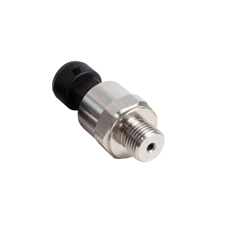
Continuous monitoring changes how municipalities manage their networks. A modern Water Pressure Transmitter outputs standard analog signals like 4-20mA or digital protocols. This continuous data stream is mandatory for predictive maintenance and intelligent pressure regulation. Complex VFD-driven networks rely on these transmitters to dynamically adjust output, compensating for fluctuating municipal demand.
Monitoring Method | Primary Application | Key Advantage | Limitations |
|---|---|---|---|
Mechanical Flow Switch | Fixed-speed agricultural pumps | Low initial cost; straightforward operation | Moving parts wear out; vulnerable to debris |
Low-Pressure Cutoff | Residential wells; simple pipe burst defense | High reliability; excellent longevity | Cannot provide variable speed control data |
Analog Pressure Transmitter | Municipal VFD stations; heavy industry | Enables precise PID control and trend analysis | Requires PLC integration and programming |
Standard electronic equipment rarely survives industrial fluid environments. You must specify core technology designed specifically for spike resistance. We strongly recommend specifying sensing elements utilizing ceramic capacitive cores. Engineers layer these ceramic structures to achieve exceptionally high burst-pressure tolerance. Unlike fragile silicon alternatives, ceramic cores flex safely during inherent water hammer events without permanent deformation.
Dirty water presents constant operational challenges. Waste processing facilities deal with sludge, scale, and organic buildup. To prevent sensor clogging, you must evaluate the physical design of the instrument. Recommend flush-diaphragm designs or specify extra-large port sizes. Flush diaphragms prevent sludge buildup from entering narrow cavities, ensuring the instrument does not become functionally blind over time.
Environmental sealing represents the ultimate reliability factor. We constantly see facilities attempting to save money by purchasing cheap commercial electronics for harsh environments. The results are always poor. Outdoor moisture, condensation, and chemical corrosion will destroy poorly rated DIY sensors in weeks. In contrast, fully potted, hermetically sealed industrial transmitters last over a decade. Selecting stainless steel housings prevents external degradation in humid pump rooms.
Installing the best hardware means nothing if you position it incorrectly. Strategic placement dictates the success of your monitoring strategy. We advise mandatory dual-point monitoring for critical systems. You install one unit on the suction side to calculate NPSH and detect fluid starvation. You place the second unit on the discharge side to detect dead-heading, closed valves, and sudden pipe bursts.
Protecting the sensor itself is equally important. Even robust instruments need mechanical assistance to survive severe hydraulic shock. Follow these implementation steps for maximum protection:
Install physical pressure snubbers directly beneath the instrument to throttle sudden shockwaves.
Mount the instrument vertically to prevent sediment accumulation on the sensing diaphragm.
Program slow-start VFD routines to ramp up motor speed gradually instead of slamming water into empty pipes.
Ensure discharge valves remain partially closed during initial startup to build back-pressure safely.
Combating human error often proves harder than fixing mechanical issues. Operators frequently bypass nuisance trips to keep production running. This automation pitfall directly leads to ruined equipment. You must implement strong anti-tampering measures. We recommend hardcoding protective trip limits deep within the PLC logic. Alternatively, physically lock out the sensor dip switches. Preventing unauthorized manual overrides ensures the safety system actually functions during an emergency.
Modern industrial operations cannot afford to treat fluid management lightly. A high-quality transmitter is not just a digital gauge. It serves as the critical input for an active, automated defense system against dry running and severe hydraulic shock. When you prioritize reliable data, you effectively eliminate catastrophic failure events before they escalate.
Base your final purchasing decisions on rigorous shortlisting logic. First, evaluate your fluid type to choose between flush diaphragms and standard ports. Second, align the sensor output with your pump drive system, utilizing analog signals for VFDs and simple switches for Direct-on-Line setups. Finally, assess your water hammer risk by looking at pipe elevation and valve actuation speeds.
Take proactive steps today. Audit your current pump stations to identify unprotected dead-heading risks. Check your suction lines for missing NPSH monitoring. If you feel unsure about proper instrument sizing, consult with a specialized application engineer immediately. Protecting your infrastructure now saves immense capital down the road.
A: A switch provides a simple binary response. It turns a circuit on or off when pressure hits a specific setpoint, acting as a basic safety interlock. A transmitter outputs a continuous analog or digital signal representing the exact pressure. Controllers use this continuous data for VFD speed adjustments and long-term trend analysis.
A: No. The sensor merely provides real-time pressure data from the suction line. To prevent cavitation, the PLC or drive controller must actively use that data to calculate the NPSH margin. The controller must then dynamically adjust the pump speed or trigger an alarm before the localized boiling occurs.
A: You should install physical pressure snubbers, which act like mechanical shock absorbers. Additionally, select sensors built with robust ceramic capacitive cores rather than fragile silicon. Finally, implement slow-ramp programming in your VFD to ensure water accelerates smoothly, drastically reducing the initial kinetic impact.