T: +86-18156545248
E: info@wnksensor.com
E: info@wnksensor.com
5F, Bldg. 2A, Mingzhu Industrial Park Hefei 230000, China
Views: 0 Author: Site Editor Publish Time: 2026-07-15 Origin: Site
Incorrectly installing a pressure sensor in an HVAC system triggers cascading mechanical failures. Field technicians often execute poor physical installation practices in commercial environments. These undetected errors generate highly inaccurate sub-cooling calculations immediately upon startup. Such data corruption leads directly to gross system inefficiencies across the entire cooling cycle. Ultimately, these compounding operational strains cause premature compressor failure. You must ensure absolute precision during your initial setup.
A truly successful installation guarantees long-term signal stability across intense seasonal changes. It protects sensitive internal micro-components from severe environmental interference. This vital protection includes defeating destructive electromagnetic noise and surviving heavy plant vibration. It also maintains unyielding mechanical integrity under extreme thermal stress. We will explore how to select appropriate signal topologies safely. You will learn to execute flawless mechanical mounting protocols correctly. We will also outline advanced EMC mitigation strategies. You will master expert-level bench testing procedures to lock in operational accuracy. Let us examine the exact engineering protocols required to safeguard your facility.
Signal Selection Dictates Topology: Choose 4-20mA for high-interference, long-distance industrial HVAC runs; reserve mV/V outputs for localized or lab environments.
Mechanical Vulnerability: Never twist the connector housing or touch the diaphragm; always apply torque strictly to the hex nut.
Transient Protection: Implement snubbers to protect against hydraulic/refrigerant "water hammer" effects.
EMC Compliance: Shielded cabling and proper grounding are non-negotiable near Variable Frequency Drives (VFDs) and ignition systems.
You must evaluate your baseline electrical architecture before touching a wrench. Signal selection dictates your entire wiring topology. Engineers typically specify three distinct electrical outputs for commercial applications. Millivolt (mV) signals remain common in highly controlled environments. They require highly regulated laboratory-grade power supplies. You cannot run mV signals beyond 200 feet reliably. They possess almost zero immunity to industrial noise.
Amplified voltage (V) outputs offer moderate noise immunity. They integrate easily into legacy controllers requiring 0-5V or 0-10V inputs. However, current (mA) loops deliver the ultimate solution for harsh plant environments. They mitigate electromagnetic interference exceptionally well over vast distances. Industry terminology often causes costly procurement confusion. A standard transducer produces various analog voltage outputs. A transmitter strictly generates a 4-20mA current output.
Output Type | Maximum Distance | Noise Immunity | Best Application |
|---|---|---|---|
Millivolt (mV) | Under 200 feet | Very Low | Laboratory, controlled test benches |
Amplified Voltage (V) | Moderate (Under 1000 feet) | Medium | Legacy controllers, light industrial |
Current (4-20mA) | Thousands of feet | Extremely High | Heavy plant environments, high EMI zones |
You must verify wetted materials against your specific refrigerants constantly. Chemical incompatibility causes rapid corrosive degradation within the sensor body. Many standard sensors use 304L stainless steel diaphragms. Highly aggressive synthetic refrigerants or ammonia blends may require specialized alloys like Haynes 214. Specifying the correct Refrigerant Pressure Transducer requires strict material validation. You must check the sensor metal against the chemical realities of your specific loop. A minor material mismatch will destroy the measuring element within months.
Facility managers must mandate strict Lockout/Tagout (LOTO) protocols universally. You must ensure the HVAC system remains entirely de-energized. Technicians cannot tap into pressurized lines safely otherwise. Always vent residual line pressure completely before removing old fittings. A sudden release of high-pressure liquid refrigerant causes immediate frostbite. Secure the working area to prevent unauthorized panel activation.
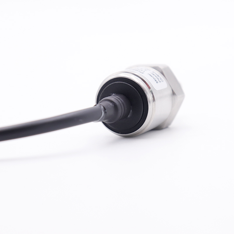
We enforce hard engineering rules for physical handling. You must never touch the pressure diaphragm directly. Touching it causes a permanent physical zero-shift. The sensing element measures microscopic deflections under pressure. Finger pressure permanently distorts this delicate architecture. We mandate using a calibrated hex wrench on the designated fitting only. You must never twist the sensor housing during installation. Twisting the cylindrical body rips delicate internal wire bonds apart. It destroys the device instantly. Always apply torque strictly to the machined hex nut.
Liquid lines routinely experience the destructive "water hammer" effect. Fast-acting solenoid valves snap shut abruptly during normal cycles. This action sends massive hydraulic shockwaves backward through the rigid piping. These transient spikes easily exceed the burst pressure limits of unprotected components. We strongly recommend integrating pressure snubbers into the piping layout. Snubbers act as microscopic shock absorbers for the fluid. They protect the HVAC Pressure Transducer from these destructive transient pressure spikes. They ensure years of uninterrupted data collection without catastrophic diaphragm rupture.
Wire counts vary strictly by your chosen signal topology. Loop-powered 4-20mA current transmitters utilize a simple 2-wire system. The exact same two wires carry both supply voltage and the return signal. Voltage and mV setups require 3-wire or 4-wire configurations. They need dedicated lines for excitation, ground, and analog signal output.
You must calculate voltage drops carefully for multi-device arrays. We rely on Ohm's Law formula for these calculations. Running multiple meters in series on a 4-20mA loop requires adequate supply voltage. The calculation multiplies loop current by total line resistance and receiver impedance. You must add the sensor's minimum operating voltage to this sum. If your power supply drops below this total threshold, the signal collapses entirely.
Industrial mechanical rooms act as incredibly hostile electrical environments. You often install an Air Conditioning Pressure Transducer near high-noise equipment constantly. Variable Frequency Drives (VFDs) and large electrical contactors emit massive electromagnetic radiation. This ambient radiation corrupts weak analog signals easily.
You must prescribe heavily shielded twisted-pair cables. Avoid running low-voltage sensor cables parallel to high-voltage AC lines. If they must cross paths, ensure they intersect strictly at 90-degree angles. You must implement strict single-point grounding rules. Grounding both ends of a cable shield creates a massive ground loop. Ground loops act like large radio antennas and amplify interference severely.
Do not install unverified hardware directly onto active systems. You must execute a standard bench test Standard Operating Procedure (SOP) first. Follow these exact steps:
Connect the device to a highly stable, isolated standby power supply.
Apply the exact specified excitation voltage listed on the engineering datasheet.
Connect a precision digital multimeter directly to the signal output terminals.
Read the null offset at zero absolute pressure. Verify this reading firmly against the manufacturer tolerances.
Basic accuracy metrics often mislead inexperienced technicians entirely. We must move beyond simple Best Fit Straight Line (BFSL) or Root Sum Square (RSS) methods. Field technicians must account for severe environmental temperature changes. You must calculate thermal zero-shifts systematically. You must also calculate thermal span-shifts accurately.
Understanding the Total Error Band (TEB) reveals the true operational accuracy. A sensor might boast an impressive 0.1% BFSL static accuracy. However, its TEB might exceed 2.0% across extreme seasonal temperature swings. Relying solely on BFSL invites disastrous diagnostic errors during peak winter or peak summer months.
Modern system diagnostics demand multiple concurrent data streams constantly. You will normally mount a Pressure Transducer immediately alongside a liquid line temperature sensor. This strategic pairing remains absolutely critical for efficiency logic.
The main system controller requires both specific datasets simultaneously. It uses the exact pressure reading to determine the refrigerant saturation temperature. It compares this theoretical value against the actual measured liquid line temperature. The controller accurately calculates dynamic sub-cooling and superheat using this mathematical gap. This precise mathematical calculation enables highly advanced predictive maintenance. It also allows variable speed compressors to adjust their output dynamically. The system achieves maximum energy efficiency automatically.
Standard off-the-shelf sensors fail prematurely in heavy-duty commercial applications constantly. These unpredicted electrical failures lead directly to expensive emergency truck rolls. Facility maintenance budgets bleed heavily from these recurring replacement costs. Replacing failing units repeatedly destroys overall plant reliability.
Advise buyers to evaluate replacements based on comprehensive engineering metrics strictly. You must analyze these specific dimensions:
Total Error Band (TEB): Demand documented proof of accuracy across the entire operating temperature spectrum.
Overpressure Ratings: Scrutinize the mechanical burst pressure and proof pressure limits carefully.
Environmental Sealing: Outdoor condensing units require strict IP or NEMA environmental ratings. IP67 represents the minimum baseline for external installations subject to heavy rain.
You must build stringent shortlisting criteria for industrial suppliers. Recommend partnering exclusively with manufacturers offering accessible, traceable calibration documentation. Demand clearly defined long-term stability metrics upfront. Look for high-grade sensors guaranteeing less than 0.05% Full Scale drift per year. Ensure they provide robust technical support assets for your maintenance teams.
A technically sound installation serves as the ultimate safeguard for overall HVAC system reliability. We discussed matching wetted materials meticulously to prevent rapid corrosion. We explored executing proper electrical shielding against aggressive EMI sources. Every single procedural step protects your vital compressor asset. Neglecting any phase guarantees wildly inaccurate diagnostic data and premature system failure.
Prompt your facility managers to act immediately on these protocols. Procurement teams must audit their current sensor failure rates today. You should consult a certified application engineer shortly to map out upgrades. Specify the correct transducer for your upcoming preventive maintenance cycle confidently. Plan your next system retrofit using these exact industrial guidelines to ensure decades of stability.
A: The distance is limited only by your loop supply voltage and total loop resistance. This total resistance includes both cable resistance and receiver input impedance. When properly powered, a 4-20mA current signal can easily reach thousands of feet without suffering signal degradation or significant noise interference.
A: You can convert the signal by placing a high-precision shunt resistor in parallel across the input terminals. The standard industrial practice involves wiring a precision 500-ohm resistor across the receiver inputs. According to Ohm's Law, this specific resistance perfectly converts a 4-20mA current loop into a 2-10V signal.
A: Zero-drift typically results from common installation errors. Applying excessive torque to the housing during mounting twists the internal components. Residual stress from localized pipe brazing heat alters the metal. Physically pressing the delicate diaphragm with your fingers or a tool during handling also causes permanent physical zero-shifts.
A: A pressure switch provides a simple binary, on/off safety limit based on a fixed threshold. It breaks or makes a circuit. Conversely, a pressure transducer provides continuous, proportional analog feedback. It sends real-time pressure measurements to the controller, allowing for highly precise dynamic system control and variable speed adjustments.